
· Week 45 · LatestVSV schedule explained
An LM2500 compressor is built for full speed.

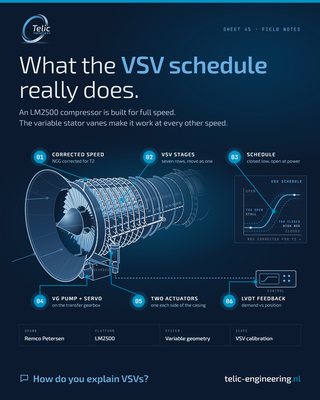
An LM2500 compressor is built for full speed. The variable stator vanes make it work at every other speed.
- 1.Input: gas generator speed (NGG), corrected for inlet temperature (T2). Output: VSV position.
- 2.Of 16 stages, seven rows are variable: the inlet guide vane row plus stages 1 to 6. LM2500+: stage 0 added, 17 stages, eight rows.
- 3.Closed at low corrected speed, opening as speed rises. Off schedule, too open: front stages stall. Too closed: NGG runs high for the power, towards overspeed.
- 4.The gearbox-driven VG pump feeds the actuators through a servo valve.
- 5.Each row's vanes are connected by linkages to an actuation ring. One hydraulic actuator per side moves all rings, via a master lever (LM2500) or torque shaft (LM2500+).
- 6.Position feedback (LVDTs on the LM2500+) is checked against demand.
How do you explain the VSVs to new operators?
· Week 44Loop checks LM
A loop check is not done when the HMI shows a number.

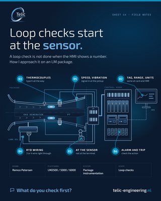
A loop check is not done when the HMI shows a number.
How I approach loop checks on an LM package:
- 1.Start at the sensor, not the terminal. Inject at the field end, so junction box, marshalling and I/O are proven too.
- 2.Tag, range and units the same on the card, in the application and on the HMI.
- 3.Thermocouples: right extension cable and connectors all the way (type K on the LM2500), polarity checked.
- 4.RTD wiring: 3 or 4 wire right through, so lead resistance is compensated.
- 5.Speed and vibration: signal in at the pickup end, conditioner matched to the sensor.
- 6.Alarm and trip: drive every signal through both. Check the action, not only the reading.
What do you check first in a loop check? And what would you add?
· Week 43Load sharing segments
A Woodward easYgen / LS-6 power management system looks complex on the single line.

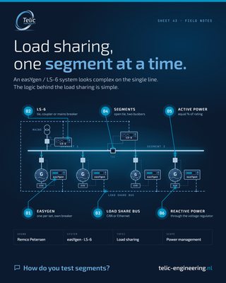
A Woodward easYgen / LS-6 power management system looks complex on the single line. The logic is simple.
How I explain it:
- 1.Each generator has its own easYgen. It synchronises and closes its own breaker.
- 2.Every other breaker that must synchronise (tie, bus coupler, mains) gets its own LS-6. It measures both sides and closes in sync or onto a dead bus.
- 3.All units talk on one load share bus, CAN or Ethernet.
- 4.Open tie breakers split the busbar into segments. Sets only share load with sets on the same segment.
- 5.kW is shared as an equal percentage of rating, not equal kW. A smaller set carries less.
- 6.kvar is shared the same way, through the voltage regulator.
How do you test the segment logic at commissioning? Breaker by breaker on the live bus, or simulated first?
· Week 42Commissioning handover dossier
A start-up is not finished when the unit runs.

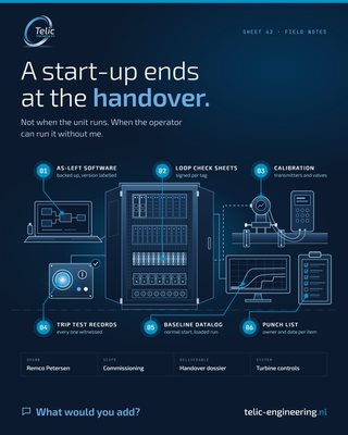
A start-up is not finished when the unit runs. It is finished when the operator can run it without me.
What I leave behind at commissioning handover:
- 1.As-left software, backed up, version and date labelled
- 2.Loop check sheets, signed per tag
- 3.Calibration records for transmitters and valves
- 4.Trip test records, every one witnessed
- 5.Baseline datalog of a normal start and a loaded run
- 6.Punch list with owner and date per item, nothing open by word of mouth
And one walk-through at the control cabinet and field instrumentation with the people who stay on site.
What do you want on your desk at handover? What would you add, or ask for first?
· Week 41Redundant controls health
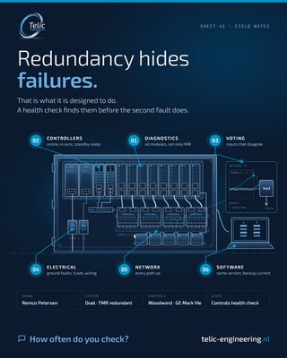
Redundancy hides failures.

Redundancy hides failures. That is what it is designed to do.
A dual or TMR turbine control keeps running with one channel down. So a failed module, a dead power supply or a drifting input can sit there for months. The second fault is the one that can trip the unit.
What I look at in a controls health check:
- 1.Diagnostics on every controller and I/O module, not only the alarms on the HMI.
- 2.All controllers online and in sync, standby ready to take over.
- 3.Voting: redundant inputs that no longer agree.
- 4.Electrical health: feeds, supplies, ground faults, loose wiring, blown fuses.
- 5.Every network path up.
- 6.Same application and firmware everywhere, backup current.
How often do you check your redundant controls, and what is on your list?
· Week 40GG exchange checks
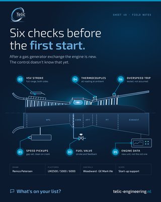
After a gas generator exchange the engine is new.

After a gas generator exchange the engine is new. The control doesn't know that yet.
What I check on the controls side before the first start:
- 1.Speed pickups. Gap set, clean signal on crank.
- 2.VSV stroke. Feedback follows demand over the full range, both actuators.
- 3.Fuel valve stroke and position feedback.
- 4.All thermocouples reading, and agreeing with each other at ambient.
- 5.Engine-specific data in the control updated to the new unit, not left from the old one.
- 6.Overspeed trip tested, not assumed.
None of it is difficult. It's just easy to skip when everybody wants the unit back online.
So what's on your list? What would you add, or check first?
VSV calibration or control upgrade coming up? Send me a message, happy to support.
Send the start date, estimated duration, scope, systems on site and location. You get availability and an estimate the same working day.
Request availabilityQuestion from purchasing or compliance? Company details, insurance, HSE and quality policies and procedures are on the Working with Telic page.
Telic Engineering B.V.
Markenplein 24, 1011 MV Amsterdam
The Netherlands
remco.petersen@telic-engineering.nl
+31 6 51345316
Telic Engineering on LinkedIn
Remco Petersen on LinkedIn
